
 The heart misses a beat, but then you realise that only you can save the Aircraft & Crew, you are in effect in full Control. First you inform the Captain & Crew of imminent Attack, and tell the Pilot which way to break away to give the Enemy Maximum Deflection. You will have already set the height & speed on the dials of the Control Box mounted horizontally at hand level to your right. You identify the Fighter and set its Wingspan on the Span handle. You now operate the left pedal which opens the ring of diamonds to the Maximum Range Setting. As your Attacker closes in, you keep him inside the Ring until he fills the Ring; he is now Framed and within Range – open fire with a 4-sec Burst. As long as you can keep him Centre in the Ring your bullets will be striking home. If he keeps coming in, he will appear to get larger; depress the right pedal to Control the Ring and keep his Wingtips touching the Diamonds. Track the Target accurately & smoothly at the same time as closing the Range with the Pedals. When the Target reaches 183M (200yds) the Graticule will not get smaller, but the Sight will still be Accurate. Keep the right foot pressed and Aim at the part of the Fighter where Hits will do the most damage.
The 100mph Gun Sight allowed a Pilot to calculate the amount of Deflection to apply. That is calculated by the Pilot, rather than estimated using knowledge of the Enemy Aircraft’s angle off Tail (the angle between Flight Paths), the percentage of speed due to this angle, or if it is Climbing or Diving. The angle/fraction of Enemy Speed to allow had to be memorised i.e. at 90° allow full Enemy Speed. at 45° – ¾ of Enemy Speed (8 angles in total). As an example at 90°, with a crossing Aircraft in the Gun Sight, full Enemy Speed would be allowed for at 300 mph, resulting in the Gunner Aiming 3 Rings in front of the Enemy. We were taught not to open Fire until within 250 yds. The Range Bars had to be set before acting on information from the Controller, as to which type of Enemy Aircraft to expect, but we were taught that a 40-ft Aircraft would fill the Gun Sight at 200-yds. Trying to condense hours of Study into a few words is not easy, it required a lot of mental work, calculation, gravity drop, allowance for side slip error, line error, and bullet trail. We practised all these exercises in Harvard AT6’s using Cameras. All good fun Diving & Attacking each other with Cameras but never “used in Anger”

 A view through the Mark III Free Mounted Gun Reflector Sight, 1st produced in 1943. Used as a Pilot Sight and a defensive Gun Sight on Aircraft. Reticle image in this Sight is produced by an optical collimator bounced off a beam splitter. The dot remains on the Target even though the viewer’s head is moved side to side. The Reflector Sight was an optical device consisting of a 45° angle glass beam splitter that sat in front of the Gunner and projected an illuminated image of an Aiming Reticle that appeared to sit out in front of the Gunners field of view at infinity and was perfectly aligned with the Aircraft’s Guns (“bore-sighted” with the Guns). The optical nature of the Reflector Sight meant it was possible to feed other information into the field of view, such as modifications of the Aiming Point due to Deflection determined by input from a Gyroscope.
The Gyro Gun Sight Mk I
Two circles were seen in the eyepiece, the one lagging behind being the Aiming Point, the leading circle being the direction in which the Guns were pointing . It was found a little difficult to locate the Target in the small eyepiece, and the Circles wandered during a high ‘g’ turn in a Fighter, but the correct Deflection Angle was presented. Bomber Command had also been testing Sights fitted in the Rear Turrets of Wellingtons. Reports from Gunnery Officers were more enthusiastic than those of Fighter Command. Once they had mastered the Technique, Turret Gunners showed a 50% improvement in Marksmanship over those using Mk III Reflector Sights. However, as there was no illumination of the Graticule, the Sight could not be used at Night. The restricted nature of the small Eyepiece was also mentioned, and the unstable nature of the Graticule was a drawback.
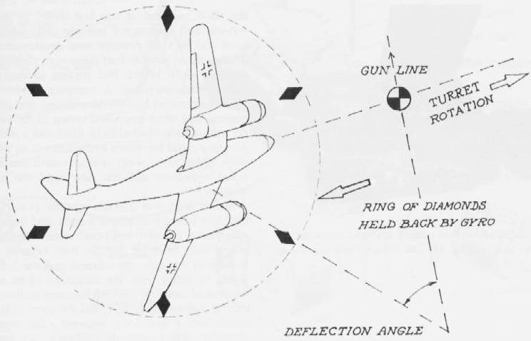
It is perhaps worth outlining again the principles by acting the part of a Trainee Turret Gunner. You 1st turn on the Switch on the end of the body. In a few seconds the Gyro will run up to 4,000 rpm. To prevent unnecessary wear, the Sight should be switched on only when Hostile Aircraft are expected. You then set the Aircraft’s height & speed on a Control Box on the left side of your Turret. Looking through the Eyepiece you will see 2 black Circles. The larger Graticule is fixed and indicates the direction in which the Guns are pointing. The smaller Ring is the point of Aim computed to allow for deflection & bullet trail. When the Turret is stationary and the Guns pointing in any direction other than Astern, the moving Graticule will be seen as being displaced from the fixed Ring by the 4-Electromagnets. When you turn your Turret to follow a Target, the Gyro will make the moving Graticule lag behind in relation to the rate of turn or rotation. This Lag, added to the bullet trail allowance, gives the Point of Aim required to hit the Target – in other words, you can’t miss – provided you can manipulate your Turret Controls accurately. The Range of your Sight is fixed at 274M (300 yds), which has been found to be the optimum – you merely place the Graticule round the Target. The Sight is protected from misting by a filter of Silica Gel, which dries the Air as it enters an inlet at the bottom of the Sight. Two adjusting Screws harmonise the Guns with the Sight. As the Elevation Screw is turned part of the anti-vibration Cradle is tilted, causing the line of Sight to be elevated or depressed. Similarly, as the Traverse Screw is turned, the Line of Sight is rotated in Azimuth.
The Gyro Gun Sight Mk II.
Farnborough devised a solution which was one of the simplest yet most effective inventions of the War: a mirror was fixed to the end of the Gyro and made to reflect an illuminated Graticule onto the reflector plate. This Graticule moved to the correct position allowing for Deflection and also incorporated a Ranging facility. The Graticule consisted of a ring of 6 small diamonds, the dia of which could be set to correspond with the Target Span. The Type of Enemy Aircraft was set on a Dial, enabling the Sight to calculate the Range. The Reflector Screen was a large glass plate 120mm (4.7 in) x 64 mm (2.5 in). Looking into the Screen, the Operator saw 2 illuminated Graticules. The 1 on the left was a Fixed Ring Graticule which could be used if the Gyro System failed, its main use being to harmonise the Guns with the Sights. In the right half of the Screen was the Gyro-controlled Ring of 6-diamonds. The dia of the Ring was adjusted by foot pedals in the Turret Version of the Sight, and by a twist grip on the Pilot’s throttle lever on the Fighter type. Both Graticules could be dimmed for Night use or used singly by switching either on or off. The height & speed setting Unit of the Mk I was found to be ideal, and could not be improved. The 1st Mk II Sights made at Farnborough were Tested by the Armament Research Unit in July 1943, and it was clear that the problems had been solved.

The lamp shines through the Graticule (G) into the Gyro Mirror, which reflects the image of the Draticule onto the Fixed Mirror (M), which reflects it through the Lens (L) onto the Mk IID Pilot’s Reflector Screen.
The new Sight had had the undivided attention of some of the ablest brains in the country, some of those taking part under Sir Melville Jones; being A A Hale, B Sykes & Group Captain Ford. Ferranti played a central role in the design & development of the complex Gyro & Electrical Components. The Sight was to be known as the GGS Mk IIC (Turret) & Mk IID (Pilot). Deliveries from a purpose-built Factory near Edinburgh began in late 1943. The Sights seemed to possess almost magical qualities. As an ex-Battle of Britain Fighter Pilot stated: ‘I look back on previous Combats where the Enemy escaped more or less intact, and realised that I could most certainly and easily have destroyed it if I had been using a good Gunsight’.

GGS Specification received from Air Ministry to Ferranti Ltd, Edinburgh, February 1943.
The Site for new Factory purchased December 1942.
Building commenced February 1943.
Factory opened June 1943
First production Sight 30th November 1943
Quantity Production commenced February 1944
Output by March 1945: 1,000
Other Companies were also involved in Production:
Barr & Stroud supplied Lenses and produced a few complete Sights.
Salford Electrical Company produced Gyro Sights to Ferranti Drawings, and other Concerns carried out Sub-contract work.
 Bomber Command was also very keen to receive the Mk IIC version. It was 1st issued to Gunnery Schools & Operational Training Units where Lectures & Air-to-Air Gunnery Practice were quickly arranged. The Gunnery Schools had been very pleased with the Mk I Sight, which had proved invaluable for Instructional purposes. A compact 16 mm sight-recording Camera had been produced, and Gunnery Training was much improved owing to the fact that no Ammunition needed to be Fired, and a record of Accuracy could be shown to the Trainee. As with the Aldis Sight, word soon spread around the Operational Squadrons and the new Sight was eagerly awaited.
At 1st there was concern over the possibility of the Sight falling into Enemy hands, and there were restrictions on Gyro-equipped Aircraft flying over Enemy-held Territory, but as they became more numerous this rule was relaxed, and the Luftwaffe began to suffer from the attention of an Enemy who could suddenly Fire with uncanny accuracy. Not that all Fighter Pilots accepted the Gyro Sight with enthusiasm at 1st, for it required a fair degree of dexterity: select Graticule brillance, set Graticule presentation, set Span level, then once the Target is presented align the Ring of diamonds to the Enemy Span. No such preparation was needed on the Mk II, but as Pilots gained experience the early scepticism vanished, and results bore witness to the Gyro’s effectiveness. Several types of German Aircraft were marked on the Dial, and Aircraft identification became even more important to Gunners. Gunners were taught to recognise the Frontal Silhouettes of German & Allied Aircraft instantly. Anyone who failed the Aircraft Recognition Test badly often failed the Course.
